@fluidcad/airfoils
Propellers, fans, wind rotors, fins, impellers and wings for FluidCAD, built
on the custom-features SDK (fluidcad/sdk).
npx fluidcad install @fluidcad/airfoils
import { propeller, fins, impeller, wing } from '@fluidcad/airfoils';
import { propellerPart, impellerPart, wingPart } from '@fluidcad/airfoils';
The four features build in a part's body. Three of them are also parts an
assembly inserts with the same values by id and mates by a connector, under
Generate Parts: propellerPart and impellerPart on axis, wingPart
on root. Fins need a body tube to stand on, so they stay a feature.
const prop = insert(propellerPart, { type: "air", blades: 2, diameter: 127 });
mate("revolute", motor.connectors.shaftEnd, prop.connectors.axis);
| feature | id | what it makes |
|---|---|---|
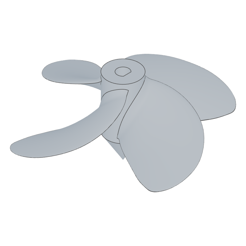
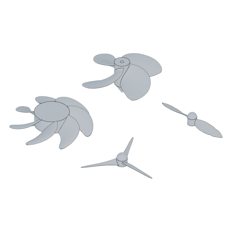
propeller | propeller | a marine (Wageningen B-series), air, axial-fan or wind rotor: airfoil blades on a hub, grown from a shaft's cylindrical face or standing on their own hub (nose, bore) |
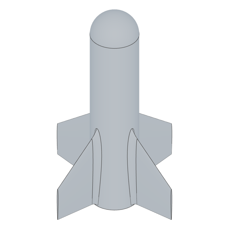
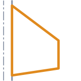
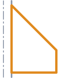
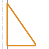
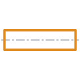
fins | fins | a ring of fins round a body tube: trapezoidal, clipped delta, delta, swept, elliptical or rectangular, with square, rounded, beveled or airfoil edges, cant and a root fillet |
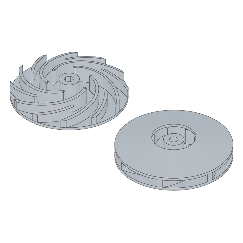
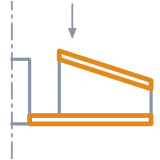
impeller | impeller | a centrifugal impeller: backward, radial or forward vanes, open, semi-open or closed, splitters, hub and bore |
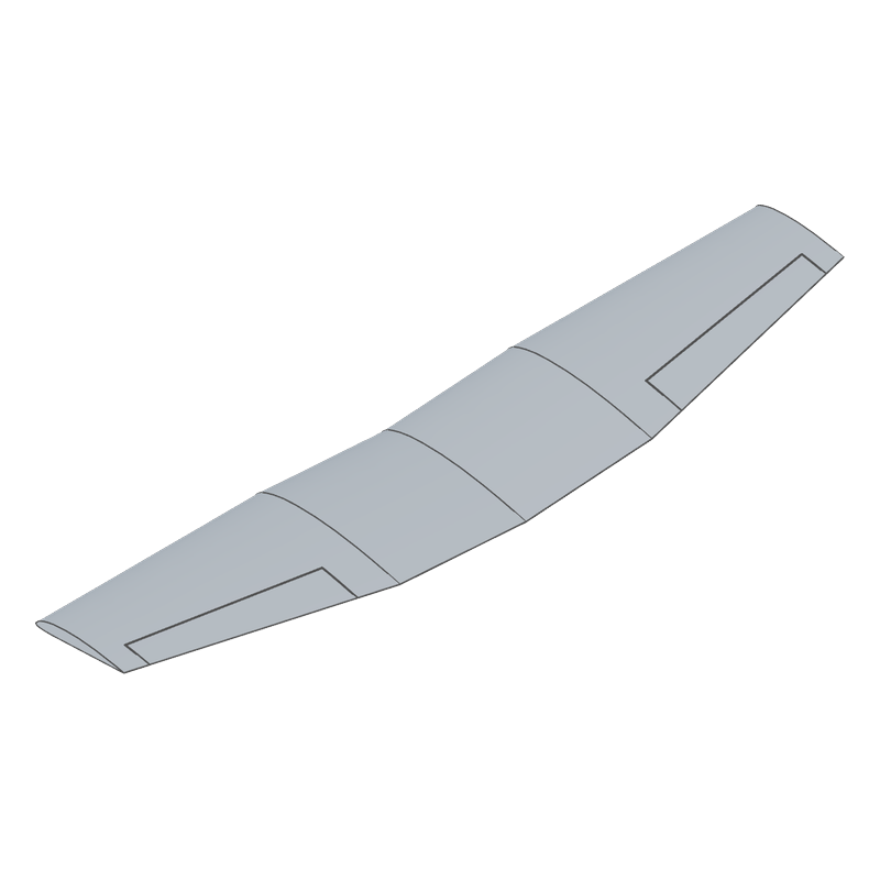
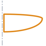
wing | wing | an RC or printed wing panel, its mirror image or the full span: NACA four- or five-digit, Clark Y or .dat airfoils blending from root to tip on a rectangular, tapered, centre + taper or elliptic planform, with sweep, dihedral, incidence and washout; solid, or a skin over lightened ribs; an aileron cut free behind a hinge line |
Each feature has a page in docs/ with its call, every value and its
buckets: propeller, fins,
impeller, wing.
Using them
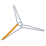
Propeller. Pick a shaft's or a hub's outside (cylindrical) face and the blades grow out of it and fuse into it, centred on the face; pick a planar face, an axis or a connector — or nothing, for the Z axis — and the feature builds its own hub there. The Type cards pick the laws the blades follow:
| type | chord | thickness | section | pitch |
|---|---|---|---|---|
| Marine | B-series, sized by the expanded area ratio | B-series t/D = A − B·Z | ogival, flat face | constant; reduced at the root for 4+ blades (B-series) |
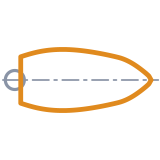
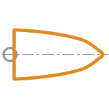
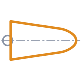
| Air | classic, elliptic, tapered, straight or paddle planform, sized by c/D at 0.75 R | 20 % → 8 % | Clark Y | constant |
| Fan | as Air | 8 % → 5 % | bent plate, 6 % camber | constant |
| Wind | Schmitz's optimum for the design tip speed ratio and lift | 24 % → 12 % | NACA 4412 | Schmitz twist |
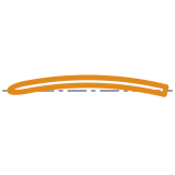
The Section tab overrides the section (NACA 4-digit, Clark Y, ogival, plate), its camber and the thickness. Skew sweeps the blades back along their pitch helix, rake leans them aft, Rotation picks a right- or left-handed rotor, and the root fillet flares the blades into the hub.
propeller({ blades: 4, diameter: 120, pitchRatio: 0.9, ear: 0.7, skew: 20, nose: "cone", noseSide: "back" });
propeller(select(face().cylinder()), { type: "air", diameter: 120, fillet: 1.5 });
Fins. Pick the body tube's outside face. The fins' root trailing edges sit
at the face's end (or offset from it; Flip for the other end), leading edges
pointing along the tube.
Impeller. Pick a planar face for the back plate, an axis or a connector, or nothing for the XY plane; the eye faces out of it.
Wing. With nothing picked the root lies on the XZ plane at the origin: the chord runs aft along +X from the root's leading edge, the span out along +Y (a left panel's along −Y), Z up. Pick a planar face (a fuselage's side), an axis or a connector and the root stands on it, the span out along its normal and up along the face's Y, which is the world's up made square to it, so a wing on a fuselage's side stands upright. Rotation turns the wing about its span, Root offset sinks the root in. Panel builds the right panel, the left one (its mirror image) or both, joined at the root: a pair to print, or a one-piece wing.
The planform is the panel's span (root to tip), its root and tip chords, and for a centre + taper wing how far out the constant-chord centre runs. Sweep is the quarter-chord line's, the line lift acts along and the sections twist about: at 0 a tapered wing's leading edge still sweeps back a little. Dihedral raises each section, which stays streamwise (parallel to the root, so two panels meet face to face); incidence is the root's angle of attack, washout twists the tip nose down by so much (over a centre + taper wing's outer panel only).
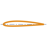
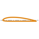
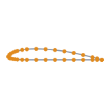
The airfoil is a NACA designation (four digits, 2412, or five, 23012,
and 23112 reflexed for a flying wing), a Clark Y of any thickness, or
coordinates pasted from a .dat file, in Selig's or Lednicer's format as
airfoil databases give them. A different tip airfoil blends in from the
root's along the span. The trailing edge opens to a printable thickness.
A wing is solid (a foam core, a solid print) or a ribbed shell: a skin of set thickness over ribs spaced evenly from the root to the tip, root and tip ribs counted, with lightening holes sized to the rib's depth where each stands. Each rib stays whole across its deepest part, a sixth of the chord round its thickest point, where the bending loads run and a spar goes. The aileron (or a flap) is cut free between two stations behind a straight hinge line, with a gap all round, walled on both sides in a shell, and kept as a body of its own or cut away.
wing({
  span: 600, rootChord: 200, tipChord: 140, washout: 2.5, naca: "2412", tipAirfoil: "naca", tipNaca: "2410",
  structure: "shell", ribs: 7, aileron: true,
});
wing({ panel: "both", planform: "centre", span: 450, rootChord: 180, tipChord: 120, airfoil: "clarky" });
wing(select(face().onPlane("xz", -30)), { span: 300, rootChord: 140, tipChord: 90 });
wing({ planform: "elliptic", airfoil: "dat", dat: 'CLARK Y\n1.0000 0.0006\n0.9500 0.0149\n…' });
Every feature names its faces in the standard buckets: blades, fins and vanes
are side faces; a propeller's and an impeller's hub back is the start, a
propeller hub's front the end, bores internal; a fin's tip is its end. A
wing's root is its start and its tip its end, its skins (and the aileron's)
are side faces, and its bays, ribs and holes internal; it also names
hingeFaces and aileronFaces. Each feature's page in docs/ lists its
buckets.
A spar and a servo bay are a sketch and a cut after the wing: they differ too much from one model to the next to be its values. A spar follows the dihedral: draw it on the root's plane turned up by the dihedral (and set a little behind the root, so the tube opens cleanly through it), and cut out along it. A pocket is a sketch under the wing, cut up into it. In a ribbed shell a plain cut opens into the hollow bay it reaches: the tube bears in the ribs it passes through (whole round their deepest part), but a pocket has no walls or floor of its own, so model them if the servo needs them.
import { part, plane, sketch, circle, line, cut, xAxis, yAxis } from "fluidcad/core";
import { coincident, diameter, distance, fix, horizontal, vertical } from "fluidcad/constraints";
import { wing } from "@fluidcad/airfoils";

export const panel = part("Wing panel", () => {
  const dihedral = 3;
  wing({ span: 600, rootChord: 200, tipChord: 140, dihedral, structure: "shell", ribs: 7 });

  // The spar: an Ø8 tube 28 % of the root chord aft (56) and midway up the
  // section (3.6), on the root's plane set 1 behind the root and turned up
  // by the dihedral, cut 450 out along it.
  sketch(plane("xz", { offset: 1, rotateX: dihedral }), () => {
    const tube = circle([56, 3.6], 8);
    distance(tube.center(), yAxis(), 56);
    distance(tube.center(), xAxis(), 3.6);
    diameter(tube, 8);
  });
  cut(450);

  // A servo pocket, 13 × 24, from underneath: drawn on the XY plane, below
  // the wing there (the dihedral lifts its lower skin to about 7 by 250
  // out), and cut up to 20, about 13 into the wing.
  sketch("xy", () => {
    const b = line([74, 240], [87, 240]);
    const r = line([87, 240], [87, 264]);
    const t = line([87, 264], [74, 264]);
    const l = line([74, 264], [74, 240]);
    coincident(b.end(), r.start());
    coincident(r.end(), t.start());
    coincident(t.end(), l.start());
    coincident(l.end(), b.start());
    horizontal(b);
    vertical(r);
    horizontal(t);
    vertical(l);
    fix(b.start(), [74, 240]);
    distance(b.start(), b.end(), 13);
    distance(r.start(), r.end(), 24);
  });
  cut(-20);
});
For the left panel (panel: "left", along −Y) turn the plane and cut the
other way: plane("xz", { offset: -1, rotateX: -dihedral }) and cut(-450).
Geometry
Blades are drawn as on a propeller drawing: at each radius r the section
(in chord coordinates) is set at its pitch angle φ = atan(P / 2πr) on the
unrolled cylinder, skewed back along the pitch helix and raked, and wrapped
back on the cylinder of radius r (θ = u / r). The wrapped sections are
fitted with B-splines that share one parametrisation and lofted into a smooth
blade, its ends capped on their own cylinders and sewn into a solid. A
rounded tip closes to a point at R; a square tip runs past R and is cut at
the tip circle. Inside the hub the blade carries on (steepening with the
helix) and is clipped at the hub's ends.
Section radii grow geometrically from the root (at most 1.4 times a step) and cluster towards the tip: a smooth loft through unevenly spaced sections overshoots and folds. The root fillet is a flare built into the sections — each one stretched by the flare on every side, f at the hub blending to nothing at 2f — rather than an OCCT fillet, which fails on the thin trailing edge.
Sections (lib/airfoil.js): NACA 4-digit (y_t = 5t(0.2969√x − 0.126x
− 0.3516x² + 0.2843x³ − 0.1015x⁴) round its mean line), Clark Y (NACA TR 628
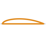
ordinates, splined over √x), ogival (flat face, elliptic nose, parabolic back,
thickest at the B-series' point) and a bent flat plate; each with a minimum
trailing-edge thickness.
Wings (lib/wing.js) are built from sections in chord coordinates,
scaled by the chord, turned by the twist about their quarter-chord point,
set on the swept quarter-chord line and raised by the dihedral, each in its
streamwise plane. A rectangular or tapered panel is a ruled loft between its
root and tip sections, the surface a hot-wire cutter gives, so the blend and
the twist run straight between them; a centre + taper wing is two such
panels joined on the break's section; an elliptic wing (chord
c0·√(1 − (y/S)²), its quarter-chord line straight) is a smooth loft through
14 sections crowding towards the tip and closing to its tip point.
The NACA five-digit mean lines follow Abbott & von Doenhoff's tables, scaled to the design lift; the reflexed lines (third digit 1) carry no pitching moment, which the tests check by thin-airfoil theory. Coordinates already over the chord are kept as given, their reference line with them; others are set square. Both sides are resampled, splined over √x, at the cosine stations every section shares, so any two blend and loft together.
A shell's void is each section offset inward by the skin along its normals, closed where its sides come 1.5 skins apart towards the trailing edge (the wing is solid aft of that), and resampled at the same stations; where the sections grow too thin for it (an elliptic tip) the void and the ribs stop short. Each bay between two ribs is lofted between the void's sections at their faces (exactly the void's surface on a ruled panel), the lightening holes are fused into the bays they join, and the wing is its outer solid with the bays as cavities: no boolean between the skin and the void, which would test every bay against the skin for nothing. The lightening holes run in a row midway up each rib, each sized to the depth where it stands, clear of the rib's deepest part and of the hinge web. The hinge line is straight between its end stations, the gap cut square to it.
Impeller vanes (lib/impeller.js) follow the point-by-point method,
dθ/dr = −1 / (r·tan β), with β running linearly from β1 at the eye to β2 at
the rim (a constant β is a logarithmic spiral). The vanes are seated on the
plate and under the shroud and glued to them.
Sources: Oosterveld & van Oossanen (1975) and Kuiper (1992) for the
Wageningen B-series; Gasch & Twele, Wind Power Plants, for Schmitz's
optimum; Abbott & von Doenhoff, Theory of Wing Sections, for the NACA
four- and five-digit sections; Stepanoff and Gülich for centrifugal vanes;
OpenRocket's fin planforms; the UIUC Airfoil Coordinates Database for the
Selig and Lednicer .dat formats.
Layout
fluidcad.json   the package block (@fluidcad/airfoils)
docs/           a page per feature (propeller, fins, impeller, wing): its call,
                values, frames, buckets and its generated part
features/       the four features, their icons/ and pictures (img/: SVG, the rotor types PNG)
  lib/            plain ES modules the features import
    airfoil.js      sections in chord coordinates: NACA 4- and 5-digit, Clark Y, .dat
    blade-math.js   radial laws: B-series, planforms, Schmitz, pitch, section radii
    blade.js        sections wrapped on their cylinders, the fillet flare
    rotor.js        the dialog's values as a blade to build
    fin.js          fin planforms and cross-sections
    impeller.js     vane camber lines and outlines
    wing.js         wing planforms, twist, dihedral, the skin's void, ribs, the hinge
    occ-build.js    OpenCascade construction: splines, lofts, booleans, hubs, bores
    placement.js    the frame a feature stands on: cylinder, face, axis, connector;
                    the frame it publishes (axis, root)
parts/          the generated parts (definePart): propeller, impeller and wing,
                each its feature with its frame as a connector
                and two examples: a rocket with fins, and a drone propeller
                that takes its size (5x3, 5x4.5, 6x4, 7x5) as configurations,
                inches as props are sold
These stay in the workspace and never ship: tests/ (vitest unit tests for
features/lib), tools/ (the scripts that draw the icons) and the npm files.
Development
npm install
npm test            # unit tests
npm run typecheck   # checkJs over the workspace
npx fluidcad pack   # → fluidcad-airfoils-<version>.fluidpkg
Pictures: the flat ones — option cards and the per-value diagrams — are SVG,
drawn straight from features/lib by node tools/icons/generate_svg.mjs. The
dropdown icons and the rotor-type cards are rendered in Blender: node
tools/icons/export_shapes.mjs writes the geometry they use, then in Blender
(through the MCP, or headless)
exec(open('tools/icons/generate_propeller_icons.py').read()); main() — it
draws in a scene of its own — and python3 tools/icons/sheet.py for contact
sheets. Headless there is no window to switch scenes in, so start empty and
name the scene for it: Blender -b --factory-startup --python-expr "import
bpy; bpy.ops.wm.read_factory_settings(use_empty=True);
bpy.context.scene.name = 'PropellerIcons';
exec(open('tools/icons/generate_propeller_icons.py').read()); main(['wing'])".

 Trapezoidal
 Clipped delta
 Delta
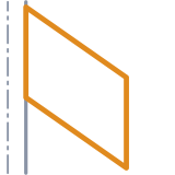 Swept
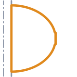 Elliptical
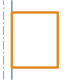 Rectangular
 Square
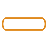 Rounded
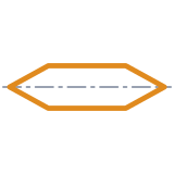 Beveled
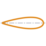 Airfoil

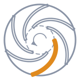 Backward
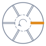 Radial
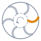 Forward
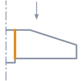 Open
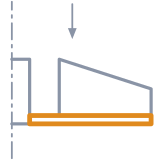 Semi-open
 Closed
 None
 Round
 D flat
 Hex

 Marine
 Air
 Fan
 Wind
 Classic
 Elliptic
 Tapered
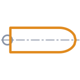 Straight
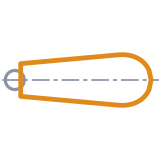 Paddle
 Auto
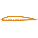 NACA
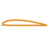 Clark Y
 Ogival
 Plate
 None
 Cone
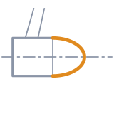 Dome

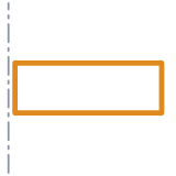 Rectangular
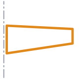 Tapered
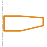 Centre + taper
 Elliptic
 NACA
 Clark Y
 Coordinates
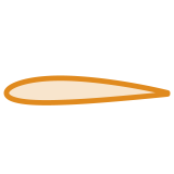 Solid
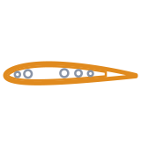 Ribbed shell